
Embedded Coder module
- May 17, 2017
- 4 min read
This blog is about Equalis Embedded Coder module. This module generates targeted C code for wide range of Microchip PIC microcontrollers and dsPIC Digital Signal Controllers from a diagram in Xcos. The approach involves very simple steps, and it is more reliable and time-saving than the traditional approach. I will show you how to implement an open-loop sensored brushless DC electric motor control algorithm in Xcos and how to generates working program for Micrchip dsPICDEM MCLV Development Board for this algorithm.
I will use the Microchip dsPIC Digital Signal Controller (DSC) for this example since it has a sufficiently high performance and incorporates the necessary peripherals such as pulse-width modulation (PWM) modules and fast and flexible analog-to digital converters (ADCs). Figure 1 shows the basic structure of the targeted hardware system.
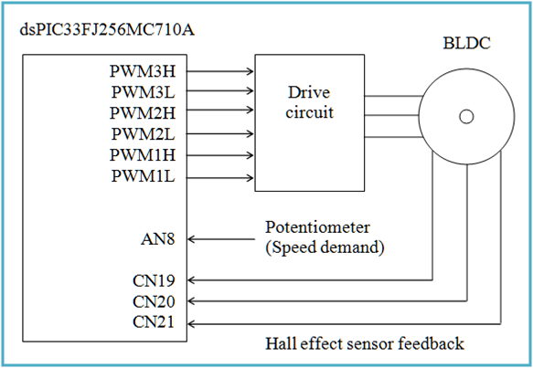
Figure 1: The block diagram of the targeted hardware system
The dsPIC DSC runs a control algorithm. This algorithm receives a speed demand from the potentiometer via an analog-to-digital (A/D) converter and the Hall effect sensor feedback, and produces a pulse-width modulation (PWM) signal for the drive circuit to control the motor speed. Let's look at more details of the algorithm.
There are two phases to the motor control program. First, the initialization is performed and we wait for 500 ms in order for the bootstrap capacitors to charge. Then the open-loop BLDC control algorithm is executed. The A/D interrupt handler reads the speed demand from the potentiometer regularly and loads its value into the PWM duty cycle registers, which is how the speed of the motor is controlled. The Hall effect sensors are connected to the Change Notification (CN) Pin of the DSC. As the rotor spins, the position of the rotor magnet changes and the rotor enters a different sector. At this moment, a CN interrupt handler reads the Hall effect sensors and using the obtained values from the look-up table updates the Override Control register (OVDCON). This action ensures that the right windings are excited and the motor continues to spin. If a PWM fault interrupt (FLTA) happens during the algorithm operation, the interrupt handler stops the motor and disables other interrupts. Figure 2 illustrates the algorithm, and Figures 3-5 shows the diagrams for the algorithm.

Figure 2: The open-loop BLDC control algorithm

Figure 3: The Xcos diagram for A/D interrupt handler

Figure 4: The Xcos diagram for Change Notification interrupt handler

Figure 5: The Xcos diagram for PWM fault handler
Figure 6 is the diagram for the first phase of the program operation to charge the bootstrap capacitors and the transition to the next phase, and Figure 7 is the diagram to write the initial values to the A/D module configuration registers.

Figure 6: The Xcos diagram for the first phase and the transition to the second phase of the program operation

Figure 7: The Xcos diagram for A/D initial values
Now that we have created diagrams for all the parts of the algorithm, we put them together. We simplify the diagram by using superblocks, and assign distinct labels to each of them. We also associate regular input and output ports of each superblock with hardware registers or global variables. If a regular port is unconnected, it is connected to a pl_Gound_g block or a pl_Terminator block, and the label to the incoming/outgoing link is assigned. Figure 8 is the diagram containing all the parts of the algorithm.

Figure 8: The Xcos diagram for the algorithm
Let's check if the algorithm diagram works as expected by simulating it. We create the top level diagram as shown in Figure 9. The larger superblock, SENSORED_BLDC_CONT, is for the controls algorithm and the smaller one, MCU, is for the hardware for the simulation purpose.

Figure 9: The Xcos diagram for the algorithm
The result is given in Figure 10. The bottom graph is the zoomed-in image of the top graph. You can see three oscillating curves in black, green and red for a, b and c phase currents, yellow for the rotor angular speed, light blue for the rotor angle and dark blue for sectors. The result indicates the mechanism of the open-loop sensored BLDC motor control as expected.


Figure 10: The simulation result of the open-loop BLDC control algorithm. The bottom is the zoomed-in image of the top graph.
Here is the list of Microchip products used for this demo
dsPICDEM MCLV Development Board (DM330021) with dsPIC33FJ256MC710A Plug-In Module (PIM). The board also contains the driver circuit and the potentiometer
A 24-Volt 3-phase Brushless DC motor with Hall-Effect sensors (AC300020)
MPLAB ICD 3 In-Circuit Debugger/Programmer
A 24-Volt external power supply (AC002013)
and Figure 11 shows how the device is set up.

Figure 11: Device setup
Figure 12 is the Xcos diagram at the very top level for the embedded code generation. The superblock represents a program for a DSC/microcontroller, and the right blocks are for configurations.

Figure 12: Top level Xcos diagram
We specify the configuration of the target platform by adding a pl_PIC_Core block from Microchip PicMicro palette to the diagram and set its parameters. This has a nice GUI with five buttons to simply configure the target with the automatic consistency checking feature. If the processor name entered is not in the module's database, the block will show a warning and try to load the processor definitions from MPLAB IDE X. Or if the value for "Desired system frequency Fosc" (button 3) is not reasonable, then the block will give a warning and may change to the closest reasonable value. Also we add pl_PIC_MCPWM, motor control pulse width modulation (MCPWM) module configuration block, and pl_PIC_GPIO, general purpose input/output (GPIO) port configuration block. The GUIs of these blocks are given in Figure 13.


Figure 13: GUIs for pl_PIC_Core, pl_PIC_MCPWM and pl_PIC_GPIO blocks
Here is how to generate targeted C code. First click on the main superblock, and select Tools->Equalis Embedded Coder in the menu bar. Choose an output directory path. Then the code generation process starts. Once it ends, go to the directory and you will find various files. One of them is the hex file. This is generated automatically during the process using Microchip MPLAB XC16 compiler, and it can be uploaded into the dsPIC DSC. The source code is also available in the directory. Figure 14 shows the directories and generated C code.

Figure 14: Generated code
This simple, time saving and flexible yet reliable method to generate target code will help engineers with rapid prototyping.


Comments